|
Highest SPL to date 150.1
Click for larger Image
Source
Pioneer DEH-P8000R
High End
4 Factory 6x8
Amplification
Rockford Fosgate Punch 800a2
Deck's MOSFET High Output 45x4
Sub woofers
Four 12" Kicker Competitions C12c
Power
22' Phoenix Gold 4 gauge power
6' Phoenix Gold 4 gauge ground
10' Phoenix Gold 8 gauge power
5' Phoenix Gold 8 gauge ground
Phoenix Gold 12 gauge speaker wire
Phonic Gold gold plated crimp connectors
Phoenix Gold three 4 gauge to four 8 gauge fused distributor
Monster Cable 4 gauge in-line fuse holder
Monster Cable 4 gauge to four 8 gauge unfused distributor
Stinger 1.0f LED voltage display Cap
80 Amp AGU Fuse
Two 60 Amp AGU Fuses
10 Amp AGU Fuse
Two .20 Amp 4" fans
Stock Alternator
Stock Battery
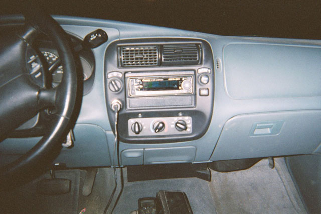
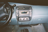
| For the source unit in this vehicle Scott and I talked for a while
about specs and prices and decided to go with the Pioneer DEH-P8000R.
This is the highest model before jumping into Pioneer's Premier line of
CD players. We have motorized face place. Full Color DOT Matrix
display with a few different visually and a pile of user adjustable features.
The hardest thing about getting the new deck installed was just simply
removing the old one. It would have been a lot easier if I would
have had the correct tools. The factory radio has a theft lock on
it. So a person has to shove 4 pieces of tough wire to disengage
the clips and in theory the radio should slide right out. Once finally
removed the installation with the dash kit and wiring harness went very
smoothly. After I had it all wired in and installed nice and neat
everything worked just as it should have except for the sound. There
wasn't any. This due to the factory amplifier. |
Click for larger Image
|
|
Click for larger Image
|
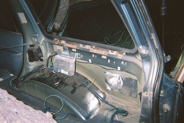
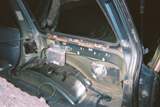
In order to get the internal amplifier of the pioneer to work with
the factory speakers I had to get to the factory amp and by pass it.
Ford had to go and locate this device behind the plastic panel on the rear
right side of the vehicle. The panel was kind of a pain to remove
but easier then the factory deck. Once removed I had to search the
internet for quite sometime to find the correct wire colors for the by
pass since I did it manually. The only advantage I can think of that
came from removing the panel other then by passing the amp was that it
made running the RCA a lot easier then trying to tuck and poke. In
the picture you can see the disconnected factory amp and then the pair
of RCA's and the remote turn on lead. For more information on the by-pass
go here |
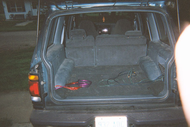
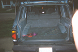
| Here you can see the back hatch with all of the wires that were ran
throughout the vehicle for power, remote turn on, and the RCA's.
This shot was taken after putting the panel covering the factory amp back
in place. |
Click for larger Image
|
|
Click for larger Image
|
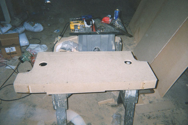
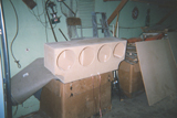
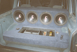
This is the finished un covered enclosure for the four 12" Kicker Competitions.
It is made out of 3/4" particle board with only one divider making for 2 subs per
enclosed air space. It is braced, wood glued, screwed, and silicone
caulked to create the best low frequency reproducer possible. The
enclosures are approximately 3 cubic feet per side. The comps recommend
1.75 per sub or 3.5 per side so it is a little smaller then recommended
but I compensated for that later when I stuffed it with 5 pounds of poly-fill. |
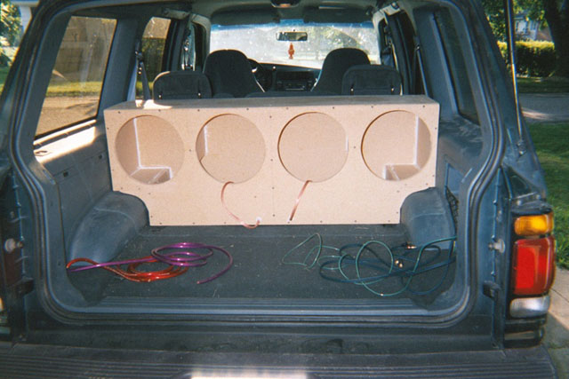
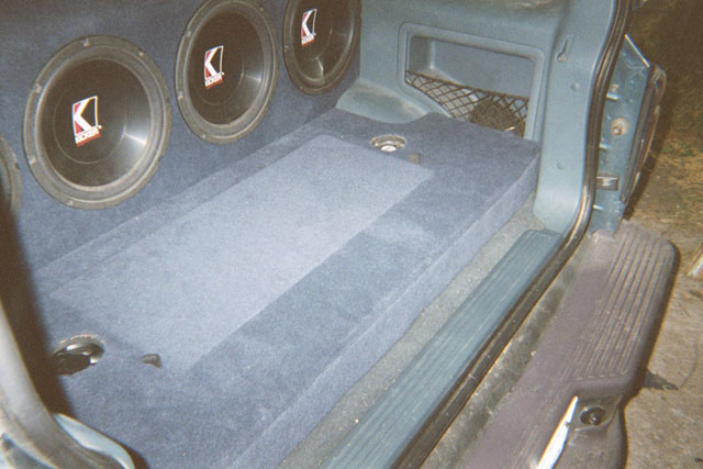
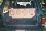
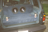
| Here you can see how the sub enclosure fit in the explorer. It
was designed to fit perfectly over the wheel wells. It does not obstruct
the rear view mirror at all due to the fact that the top of the box is
even with the top of the rear seats. The rear seats will still fold
forward for storage but the system is not designed to be removable. |
Click for larger Image
|
|
Click for larger Image
|
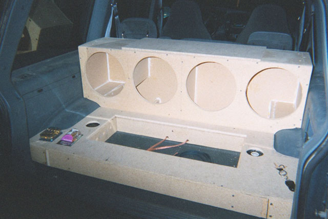
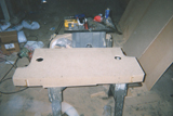
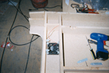
This is the finished uncovered amp rack enclosure. It will be
housing all the wiring, amplifier, capacitor, relay, and fuses. I
made the amp rack out of a combination of 3/4 and 1/2 particle board.
This required the most thought before building since I had to know exactly
how all the wires were going to be ran within the enclosure. |
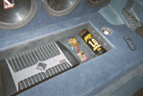
| This is a shot from the underside of the amp enclosure. You can
see how the fan was attached a little bit better. Here you can also
see how I went about bracing and drilling for the wiring. The intake
and out take fans are either blowing or sucking into independent enclosures
so all the air being moved will flow over the amp and capacitor. |
Click for larger Image
|
|

Click for larger Image
|
Here you can see the install coming together. I have both the
sub box and the amp rack installed with some of the electrical components
that are going to be used very soon setting on the left side of the picture |
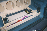
| In this shot I have the component shelf cut with the 1f Stinger capacitor
mounted. You can also see a lot of the wiring since I do not have
the top panel in place. This shot also shows that the inner sides
of the amp area is painted black. I actually did this while it was
in the vehicle. Just took a lot of newspaper and cardboard to prevent
getting paint on anything factory. |
Click for larger Image
|
|
Click for larger Image
|
Now the install is carpeted. This was an all night project that
might have gone a little faster had I not consumed a few to many Milwaukee's
Best.
I had to hold off on the installation of the carpet a couple of days
to wait for it to get in. We had it special ordered to get as close
as possible match with the factory color. Not a perfect match but
still came out looking great.
I also went and screwed 2 of the subs in just to get an idea of what
it is going to look like when completed. |
| Just another shot of the same thing but with me the happy (intoxicated)
installer. If you look close you can see the sun coming up in the
distance. Just goes to show my extreme dedication to car audio excellence. |

Click for larger Image
|
|
Click for larger Image
|
This picture was taken the day ups finally brought the amp. Nothing
is wired here. I just set the Rockford Fosgate 800a2 in place
to give me an idea of how it was soon to look.
Above the left fan you can see the cover that is going to be places
aver the fan hole for appearance and protection of the fans. I did
not find another one just like that once until after I had used up all
of my film so I do not have any pictures of them both installed. |
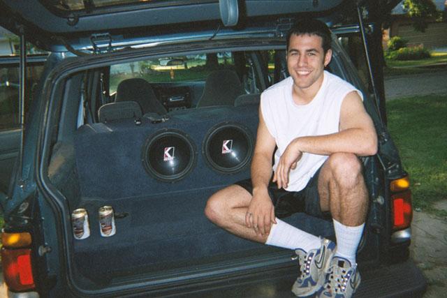
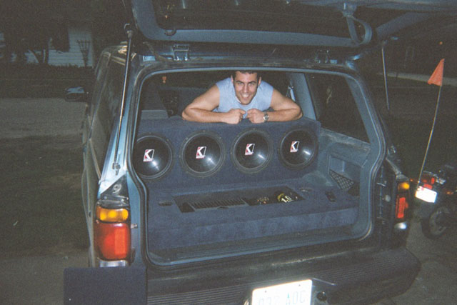
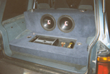
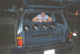
| Here I am again proud as can be of the loudest creation to date.
I now have all 4 subs installed. Everything is wired and functioning.
I have the component cover removed and setting next to the explorer to
kind of show off the goods. |
Click for larger Image
|
|
Click for larger Image
|
Now for a closer shot of the install. The amplifier had to be
half way flush mounted to make plenty of clearance for the cover and the
air that in theory had better be flowing over it. This made adjusting
the gains nice and difficult but since the gains are currently turned as
low as they go it was not to tough. |
| This is the best shot of the components that I took. The positive
fused power distribution is in the top between the capacitor and the amplifier
while the negative unfused distribution is below it. Notice the L.E.D.
display on the capacitor monitoring the system voltage when ever fluctuation
is present. |
Click for larger Image
|
|

Click for larger Image
|
This is what everything looks like with the completed cover in place
covering really expensive stuff. I put two little nylon straps on
each side to make removal of the panel much less stressful. |
|