Click for Larger Image
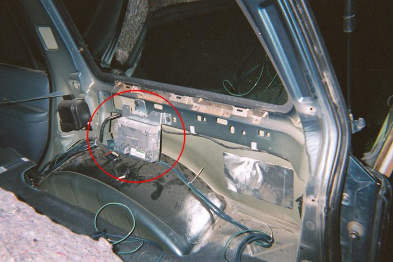
The reason for this is simple. Your amplified signal from your new deck intended to power your speakers has found a road block on it's trip. This 'block' is the factory amplifier.
It is located behind the rear right plastic paneling.(Passenger Side)
In order to get your deck playing like you want to using existing factory wiring you are going to have to by pass this factory amp. There are 2 ways to do this: 1.. Either buy yourself a harness that will simply plug into both the input and output plugs after you disconnect them from the factory amp or 2.. Hard wire these two sets of wires together manually. (This is what I did), (This can be a bit of pain with out the wire colors), (Also how I had to go about doing it. Arg!)
You are going to save some money if you just butt connect or screw the bypass together but you are also going to be making things much harder to change back to the way they were then it would be if you used the harnace method.
Tools
Philips Screw Driver
7/32" Socket
T-50 Tork Socket
Butter Knife (optional)
Wire Stripers (depends)
Wire Crimpers (depends)
Electrical Tape (depends)
Getting it done
Decide if you are going to use a harnace to by pass your factory amp
or if you are going to cut the wires and reconnect them.
Harnace Method
1. Get your deck/dash kit/harness for deck and get it installed ( you
should not get any sound after this. That is why this site is here)
2. Buy your harnace and have it ready.
3. Remove the Plastic Paneling (see panel removal)
4. Unplug the 2 plugs from the factory amp and connect the harnace
in between them.
5. Put the panel back in place and enjoy your new deck and the music
that it is finally producing.
Cut and Rewire Method (save about $15-20)
1. Get your deck/dash kit/harness for deck and get it installed ( you
should not get any sound after this. That is why this site is here)
2. Get either butt connectors or wire screws
3. Remove the Plastic Paneling (see panel removal)
4. Unplug the 2 plugs from the factory amp and cut them off
5. Use the wire colors and plug diagrams below as reference and strip
and connect the 2 sets of wires together.
6. Isolate the 12v + power with electrical tape to prevent arcing
Panel Removal
1. Remove the plastic cover on the top part of the seat belt and use
the t-50 to remove the bolt
2. Use the 7/32" socket to remove the clothes hanger hook about the
rear right door.
3. Pull up the carpet and the padding along the edge of the big plastic
panel to expose the 2 philips screws. Remove them.
4. Pop the rear plastic trim underneath the hatch on the floor up and
remove it
5. Now all that is holding the panel in place are the plastic push
clips. You can use a butter knife to pry them lose or just simply
pull on the panel (easier and effective)
6. You now should be able to pull the panel away from the wall and
get at the factory amp. Some maneuvering of the fold down seat and
seat belt may be required but it is rather easy.
7. When done the panel goes back in place the same way it came
off. be sure to pound the plastic connectors back in place with your
hand so the panel is not lose anywhere.
Note: If you are going to be installing any after market
amps I would suggest running the RCA's while the panel is off. There
is lots of room for doing so behind there.
In conclusion I hope that this page has help aide in your pursuit of
audio bliss
|
 |
 |
|